
Linux Analog to Digital Converter
By David Chong and Philip Chong
1. Introduction
2. Interfacing Your Computer to an ADC via
the Parallel Port
2.1 Building a Basic ADC Circuit
2.2 Reading From
and Writing To the Parallel Port
2.3 Communicating
Between the ADC and the Parallel Port
3. About the Extreme Comfort System
4. Code examples
5. Appendix
Introduction
Why read this article?
It can be a little expensive to read analog signals, for example temperature readings or light levels, into your computer. In this article we will show you (1) how Linux can use a computer parallel port and a $10 integrated circuit to read 8 analog channels at 12 bit accuracy, and (2) how we used this to build the Extreme Comfort System (ECS.)
Analog to digital conversion (ADC) can measure:
• Temperature, using thermistors
• Light intensity, using Light Dependent Resistors (LDR)
• Pressure
We can use the acquired data for applications such as:
• Data acquisition
• Data logging
• High-accuracy process control
The ECS project is an example of these applications.
Interfacing Your Computer to an ADC via the Parallel Port
Interfacing an Analog-to-Digital Converter (ADC) with Linux via the parallel port is fairly simple. There two major areas that need to be addressed - hardware and software. The hardware consists of the parallel port, an ADC, and an analog signal source. The software we programmed in 'C' language.
Below I have outlined three steps that explain how to develop and integrate both components of this useful tool.
1. Building a Basic ADC Circuit
The first step is to build the hardware. As mentioned before our hardware consists of the parallel port, an ADC, and a analog source. For my project I used a MAX186 as the ADC and an NTC Thermistor as the analog source. The MAX186 is a data-acquisition system that combines an 8-channel multiplexer and a 12 bit ADC. Refer to the MAX186 datasheet for more information. NTC Thermistors (5MMDIA 47KR) are readily available at Jaycar - CAT. NO. RN3442.
(Editor's note: A similar thermistor with a slightly different temperature coefficient from Digi-Key is BC1487-ND - Dave)
Figure 1 below shows a simple circuit diagram that converts the analog signal produced by the thermistor to a digital BCD signal, which is read by the computer via the parallel port. Figure 2 shows an example circuit I constructed using the circuit diagram in Figure 1.
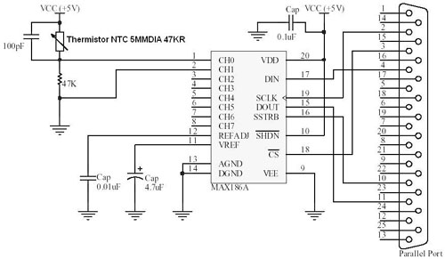
Figure 1: Simple ADC-to-Parallel Port circuit diagram
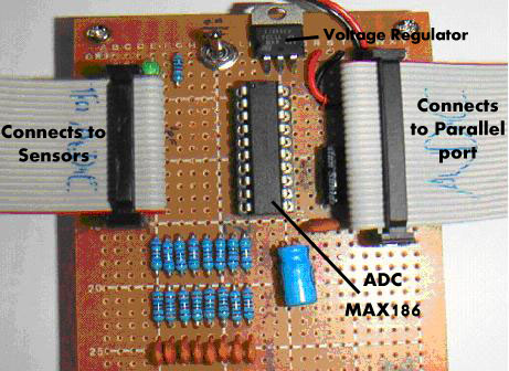
Figure 2: ADC Hardware Example
See ADC_driver.c in the Code Examples section for the actual program to operate this circuit.
2. Reading from and Writing To the Parallel Port.
Now that that hardware is built, it is time to develop the software. However before you begin to write code or even start up Linux you must gain access to the parallel port. Without this there is no way you can read or write to the ADC. Refer to "Information about the Parallel Port and SPI" in the Appendix for a brief overview on the Parallel port and how it communications to the ADC.
To gain access to the parallel port in Linux you have to setup the BIOS to support the Simple Parallel Port mode, which corresponds to the old Centronics standard. This is done by selecting the SPP or Bidirectional mode in BIOS. With the BIOS set we enable I/O using the lp_tty_start program, see the “Linux: A Clear Winner for Hardware I/O” written by Peter Radcliffe.
In addition to running the lp_tty_start program, you also need the following code snippets below. Both these code snippets are used in my ADC_driver.c code example.
-------- lp_init() --------------------------------------------
 PURPOSE - given lp number 0-2, get lp base address,
           save registers, disable interrupts.
void lp_init(short lp_num)
 { switch ( lp_num)
    { case 2 : lp_base_addr = 0x3BC ; break ;
      case 1 : lp_base_addr = 0x278 ; break ;
      default: lp_base_addr = 0x378 ; break ;
    }
   image_data    = save_data    = inb( lp_base_addr) ;
   image_control = save_control = inb( lp_base_addr+2) ;
   outb( (image_control &= 0xEF),  lp_base_addr + control_offset) ;
 }
---------------------------------------------------------------
--------- lp_restore() ----------------------------------------

 PURPOSE - restore lp port to previous state.

void lp_restore()
{  outb( save_data,    lp_base_addr) ;
   outb( save_control, lp_base_addr + control_offset) ;
}
---------------------------------------------------------------
source: “Linux: A Clear Winner for Hardware I/O,” Peter Radcliffe
Function lp_init() saves the current parallel port state , including register values. lp_restore() restores the parallel port to the previous state as saved by lp_init(). Normally lp_init() would be run at the beginning of main() and lp_restore() would be used at the end. To read and write from the parallel port use library functions inb() and outb() from #include asm/io.h.
To test a whether the I/O is working, write a simple program that toggles the output on a pin on the parallel port and use a multimeter or CRO to read the output. If the pin output toggles correctly, then the I/O works.
3. Communicating Between the ADC and the Parallel Port
Once the circuit in Figure 1 is constructed and communication between the parallel ports is established we can begin to program a simple conversion. The file 'ADC_driver.c' (see Code examples below) contains the C code that performs the conversions. However if you like to develop your own software the following paragraphs briefly describe how to initiate and read a conversion.
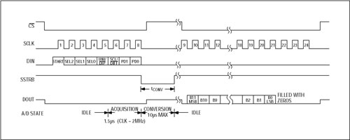
Figure 3: Internal Clock Mode Timing
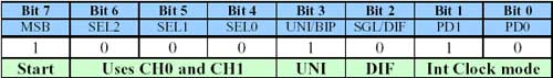
Table 2: Control Byte Configuration
As shown in Figure 3, a conversion is initiated by clocking a control byte into DIN. The format for the Control Byte is outlined in the MAX186 datasheet. For our purposes we will use the Control Byte configuration outlined in Table 2.
Once the control byte is clocked in, the SSTRB will go low which indicates the start of the conversion and then goes high when the conversion is complete. After the SSTRB goes high, the next falling clock edge will produce MSB of the conversion at DOUT, followed by the remaining bits in the MSB-first format (refer to Figure 3). If everything works correctly DOUT should clock out a 12 bit BCD which corresponds to the voltage reading at the temperature sensor. To convert the BCD to a decimal I used the following code snippet:
---------------------------------------------------------------
  int dec = 0;
  for(count=0; count<=11; count++)
  {     dec = ((tempOut[11-count])*(twopowerof(count)))+dec;
  }
---------------------------------------------------------------
* tempOut[] is a 12 integer array which contains 12 bit BCD (where
tempOut[0] = MSB and tempOut[11] = LSB).
If your DOUT outputs strange results, such as all zeros or erratic readings, (I had these problems) check your circuit wiring and make sure they follow the circuit diagram outlined in Figure 1. If you still have problems you can use a CRO to check your parallel port output to make sure they match the timing outlined in Figure 3.
About the Extreme Comfort System
My first encounter with Linux, parallel ports and ADCs occurred during my 4th year at University. The project objective was to interface to a piece of hardware via the parallel port. I decide to build an Extreme Comfort System or ECS for our project. The idea for this project occurred during one cold night at my computer desk when I noticed my hands were freezing and my eyes were strained from the poor lighting conditions. From this three main functions were developed:
1. Thermostat - Three temperature sensors monitor the ambient temperature near the keyboard and a fan or heater is activated depending on the user settings. A GUI interface displays and controls the function of the thermostat.
2. Automatic light Controller - A light sensor monitors the light level near the keyboard and computer monitor and a variable light source changes its intensity according to user settings. A GUI interface displays and controls the functions on the automatic light source.
3. Data logger - All the readings from the temperature and light sensors are stored into separate files with statistical analysis. These files can be displayed on the GUI interface.
To develop this project we used QT designer for the GUI development and the MAX186 for the ADC. We only needed to use one ADC, which converted the analog voltage signals from the temperature and light variable resistors to digital signals. The circuit design was very similar to the ADC circuit in Figure 1, except a bit more complex.
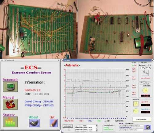
Pictures of ECS hardware and GUI
For more information about the ECS refer to my ECS website.
Code examples
Here are some real code examples.
lp_tty_start.c: this file was written by Peter Radcliffe and can be found in his article “Linux: A Clear Winner for Hardware I/O.” This I/O enabler allows access to the standard three printer ports and four serial ports but nothing else. Ensure it is owned by root with the SUID bit set (refer to Peter Radcliffe's article). To compile, type gcc -o lp_tty_start lp_tty_start.c. To run, type ./lp_tty_start ./your_program.
ADC_driver.c: will run in collaboration with the “Simple ADC-to-Parallel Port circuit” (Figure 1). Once in operation it will output the current voltage of the NTC Thermistor every second. To compile, type gcc -o ADC_driver ADC_driver.c. To run, type ./lp_tty_start ./ADC_driver.
The ECS program (complete tarball can be downloaded here) will perform the tasks described in the section About the Extreme Control System. This includes the thermostat, automatic light control, data logger and the GUI involved. To compile, type qmake -o makefile ecs.pro -> make. To run, type ./lp_tty_start ./ecs.
Appendix
Information about the Parallel Port and SPI
The original IBM-PC's Parallel Printer Port had a total of 12 digital outputs and 5 digital inputs accessed via 3 consecutive 8-bit ports in the processor's I/O space.
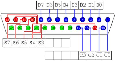
25-pin Female D-Type Connector
• Pins 9-2 (D7-0) are output pins accessed via the DATA Port.
• Pins 17, 16, 14, 1 (C3-0) are output pins, three inverted, accessed via the CONTROL Port.
• Pins 10-13, 15 (S7-0) are input pins accessed via the STATUS Port.
• The remaining pins (25-18) are grounded.
The ADC communicates with the parallel port using the SPI (Serial Peripheral Interface) protocol. SPI can be used to talk to a whole range of integrated circuits such as EEPROMs and microprocessors, so you may find the SPI part useful for other projects. In our simple ADC-to-Parallel Port circuit, shown in Figure 1, there are five wires connecting the ADC to the parallel port. They include DIN, SCLK, DOUT, SSTRB, and CS. Together they are used to to establish fast and flexible communication. For more information about SPI refer to the MAX186 datasheet.
David Chong
David Chong is a final year student at RMIT University in Melbourne
Australia. Nearing completion of a double degree in Computer Systems
Engineering and Business Administration, his interest in Linux,
microprocessors and integrated circuit was not apparent until about his 3rd
year at the university. Prompted by his senior lecturer, P.J. Radcliffe (also an author of LG)
whose relentless enthusiasm for Linux and electronics revealed how robust
and powerful the Linux operating system can be. Also a 12-week vacation employment at ANSTO at Lucas Height, NSW
introduced me to the wonderful world of microprocessors and their amazing
applications. Excited about entering into the workforce and working on some large-scale
projects, David is also interested in Wing Chun Kung Fu and music, in particular
the guitar, and hopes to create a rock band one day. ![[BIO]](../gx/authors/dchong.jpg)
Philip Chong
Philip Chong is a 5th (final) year student studying Computer System
Engineer and Business Administration at RMIT Univeristy in Melbourne
Australia.
He developed a interest in electronics and gadgets at a young age due to
fictional characters such as Batman, Robocop, and Inspector Gadget. However,
it was early in the university where he developed a keen interest in software
and hardware largely due to influence of certain lecturers including P.J. Radcliffe,
who is also an author for LG. Philip has worked with Linux for the past 3 years and his skills range
from software GUI development to programming assembly code for
microprocessors. In this free time he enjoys practicing kung fu, playing
piano and guitar, woodwork, and rock'n roll.![[BIO]](../gx/authors/pchong.jpg)
